

Harnessing solar energy efficiency is crucial for renewable energy systems. One way to maximize solar energy capture is through a solar tracking system that continuously adjusts the orientation of a solar panel to face the sun. In this project, we will demonstrate how to build a solar tracking system using ESP32, MPU6050 accelerometer, Neo 6M GPS Module, servo motors and AWS (Amazon Web Services). By combining sensor data, cloud computing and IoT capabilities, we can create an intelligent solar tracking system that optimizes energy generation.
Project Overview
Solar energy is a renewable and sustainable source of power that has gained significant attention in recent years. To harness solar energy efficiently, solar panels must be oriented towards the sun to maximize energy capture. This is where a solar tracking system comes into play. A solar tracking system continuously adjusts the position of the solar panel to follow the sun's movement throughout the day, ensuring optimal alignment and increased energy generation.
Benefits of Using Sensor Data, Cloud Computing and AWS Services:
Precision in Solar Positioning:
Traditional fixed solar panel installations rely on a static orientation, limiting their efficiency as the sun's position changes. By utilizing sensor data from the MPU6050 accelerometer, this solar tracking system can accurately track the sun's movement in real time. This allows for precise positioning of the solar panel, ensuring it always faces the sun for optimal energy capture.
Real-Time Data Processing Analysis:
With cloud computing capabilities provided by AWS, we can process and analyze sensor data in real-time. This enables us to calculate the sun's position and make necessary adjustments to the solar panel orientation promptly. The cloud-based approach eliminates the need for complex calculations on the ESP32 itself, allowing for efficient data processing and faster decision-making.
Scalability and Flexibility
By utilizing AWS services, our solar tracking system can easily scale to handle large volumes of data from multiple sensors or solar panels. AWS provides a robust infrastructure that ensures flexibility and easy integration with other AWS services, allowing for seamless expansion and customization.
Remote Monitoring and Control:
With cloud connectivity, our solar tracking system can be remotely monitored and controlled. AWS IoT Core facilitates communication between the ESP32 and the cloud, enabling seamless data transmission and control commands. This remote monitoring capability allows system administrators to track performance, receive notifications and adjust settings from anywhere, ensuring operation and maintenance.
Data Insights and Optimization:
AWS Services, such as AWS Lambda and DynamoDB, provide powerful tools for data analysis and insights. By storing sensor data in DynamoDB, we can analyze historical trends, identify patterns, and gain valuable insights into the system's performance. This data-driven approach enables continuous optimization of the solar tracking system, leading to improved energy generation and operational efficiency.
Hardware Setup:
To build the solar tracking system, we will need the following components:
ESP32 board: It will be used as the central control unit for the solar tracking system. It will be the microcontroller that acts as the brain of the system, controlling the sensors and servo motors.
MPU6050 accelerometer: The MPU6050 accelerometer will be used to measure the orientation of the solar panel. This sensor combines a 3-axis accelerometer and a 3-axis gyroscope, providing accurate motion sensing capabilities.
Neo 6M GPS module: To determine the location and obtain longitude and latitude coordinates, we will incorporate the Neo 6M GPS module into our system. The GPS module receives signals from multiple satellites to calculate the device's precise location.
Servo motors: Servo motors will be used to adjust the solar panel's orientation based on the calculated azimuth and elevation angles. Servo motors offer precise control over rotational movement, making them suitable for our solar tracking system.
Breadboard and jumper wires: We will use a breadboard and jumper wires to connect the components and create a tidy and organized circuit.
Power supply: Ensure you have a suitable power supply, such as USB cable or a battery pack, to power the ESP32 and the connected components.
Now let's proceed with the hardware setup:
Connect the MPU6050 accelerometer to the ESP32 board:
| MPU6050 accelerometer | ESP32 |
| VCC Pin | VCC |
| GND Pin | GND |
| SDA Pin (data pin) | D21 |
| SCL Pin (clock pin) | D22 |
Connect the Neo 6M GPS module to the ESP32 board:
| Neo 6M GPS module | ESP32 |
| VCC Pin | VCC |
| GND Pin | GND |
| TX Pin | D13 |
| RX Pin | D27 |
Connect the servo motors to the ESP32 board:
| Pan Servo motor | ESP32 |
| VCC | VCC |
| GND | GND |
| Signal | D18 |
| Tilt Servo motor | ESP32 |
| VCC | VCC |
| GND | GND |
| Signal | D19 |
Ensure all connections are secure and double-check the wiring to avoid any loose connections or short circuits.
Connect the ESP32 board to your computer or power supply using a USB cable or a battery pack.
The hardware setup is now complete. In the next sections, we will focus on acquiring sensor data, integrating cloud services, and implementing solar panel orientation adjustments.
Schematic

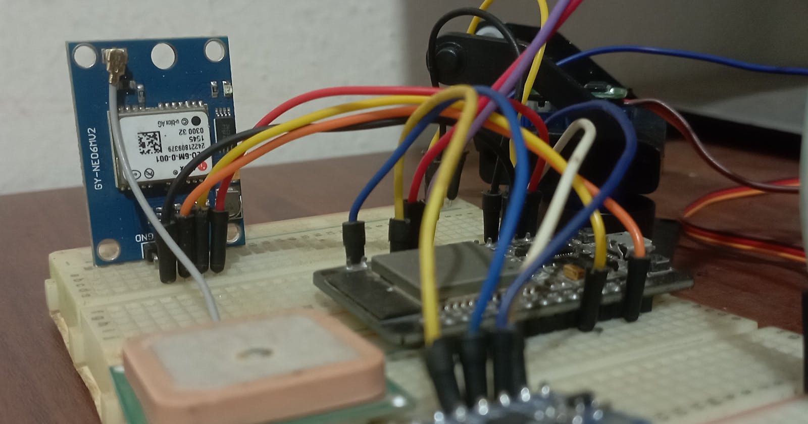
Images
Code
Sensor Data Acquisition:
In our solar tracking system, we acquire sensor data from the MPU6050 accelerometer and the Neo 6M GPS module. The MPU6050 provides accelerometer data, allowing us to measure the solar panel's orientation, while the Neo 6M GPS module provides longitude and latitude coordinates for precise location information. By using Arduino, we can interface with these sensors and extract the necessary data.
To acquire data from the MPU6050 accelerometer, we initialize the sensor, configure its settings, and then read the accelerometer data in the Arduino loop function. The accelerometer data provides information about the solar panel's tilt and orientation.
For the Neo 6M GPS module, we establish a Serial communication with Arduino to receive GPS data. By processing the NMEA sentences sent by the module, we can extract the longitude and latitude coordinates, which are crucial for calculating the sun's position accurately.
By successfully acquiring sensor data from these components, we are ready to move forward and utilize this information to calculate solar panel orientation and integrate it with cloud services for optimal solar tracking.
Calculating Sun's Position:
Now that we have acquired the necessary sensor data from the Neo 6M GPS modules, we can proceed to calculate the sun's position.
We'll use Solar Position Algorithm (SPA) from the SolarPosition library to calculate the position of the sun relative to geographic coordinates.
The sun's azimuth angle and elevation angle are obtained using the code below:
Header file:
#ifndef SOLAR_MODULE_H
#define SOLAR_MODULE_H

#include <SolarPosition.h>
#include <TimeLib.h>

class SolarModule
{
public:
    float azimuth=0;
    float elevation=0;

    void displaySolarPosition(tmElements_t time, tmElements_t date, float lat, float lon);
};

#endif
Cpp file:
#include "SolarModule.h"
void SolarModule::displaySolarPosition(tmElements_t time, tmElements_t date, float lat, float lon)
{

    SolarPosition savedPosition(lat, lon);
    time_t epochTime = makeTime(time);

    azimuth = savedPosition.getSolarPosition(epochTime).azimuth, 4;
    elevation = savedPosition.getSolarPosition(epochTime).elevation, 4;

    Serial.println((String) "The sun was at an elevation of " + elevation + " and an azimuth of " + azimuth);
}
Calculating Solar Panel Orientation:
The orientation of the solar panel is obtained from the MPU6050.
The MPU6050 IMU has both a 3-Axis accelerometer and a 3-Axis gyroscope integrated on a single chip.
The gyroscope measures rotational velocity or rate of change of the angular position over time, along the X, Y and Z axis. It uses MEMS technology and the Coriolis Effect for measuring. The outputs of the gyroscope are in degrees per second, so to get the angular position we just need to integrate the angular velocity.
On the other hand, the MPU6050 accelerometer measures acceleration. Briefly, it can measure gravitational acceleration along the 3 axes and using some trigonometry math we can calculate the angle at which the sensor is positioned. So, if we fuse, or combine the accelerometer and gyroscope data we can get very accurate information about the sensor orientation.
The Adafruit MPU6050 library is used in the calculation.
The orientation of the solar panel is obtained from the code below:
Header file:
#ifndef MPU6050_MODULE_H
#define MPU6050_MODULE_H

#include <Arduino.h>
#include <Adafruit_MPU6050.h>
#include <Adafruit_Sensor.h>


struct angle
{
    float x, y, z;
};

class MPU6050Module
{
public:
    MPU6050Module();
    angle position;

    unsigned long lastSampleMicros = 0;
    unsigned long lastPrintMillis = 0;

#define INTERVAL_MS_PRINT 1000

    Adafruit_MPU6050 mpu;

    void setupMPU6050();
    angle calculateAccelerometerAngles();
    angle calculateGyroscopeAngles(unsigned long sampleMicros);
    float getTemperature();
    void detectPitch(angle gyroscope, angle accelerometer);
    double getPitch();
    void detectRoll(angle gyroscope, angle accelerometer);
    double getRoll();
    bool readSample();
};

#endif
Cpp file:
#include "MPU6050Module.h"

MPU6050Module::MPU6050Module()
{
}

void MPU6050Module::setupMPU6050()
{
    // Try to initialize
    if (!mpu.begin())
    {
        Serial.println("Failed to find MPU6050 chip");
        while (1)
        {
            delay(10);
        }
    }
    Serial.println("MPU6050 found!");

    // set accelerometer range to +-8G
    mpu.setAccelerometerRange(MPU6050_RANGE_8_G);

    // set gyro range to +- 500 deg/s
    mpu.setGyroRange(MPU6050_RANGE_500_DEG);

    // set filer bandwidth to 21 Hz
    mpu.setFilterBandwidth(MPU6050_BAND_21_HZ);

    delay(100);
}

angle MPU6050Module::calculateAccelerometerAngles()
{
    angle accelerometer;

    /*Get new sensor events with the readings*/
    sensors_event_t a, g, temp;
    mpu.getEvent(&a, &g, &temp);
    accelerometer.x = (asinf(a.acceleration.x / 9.81));
    accelerometer.y = (atan2f(a.acceleration.y, a.acceleration.z));
    accelerometer.z = ((a.acceleration.z / 9.81));

    return accelerometer;
}

angle MPU6050Module::calculateGyroscopeAngles(unsigned long sampleMicros)
{
    angle gyroscope;

    /*Get new sensor events with the readings*/
    sensors_event_t a, g, temp;
    mpu.getEvent(&a, &g, &temp);
    gyroscope.x = g.gyro.x * sampleMicros / 1000000;
    gyroscope.y = g.gyro.y * sampleMicros / 1000000;
    gyroscope.z = g.gyro.z * sampleMicros / 1000000;

    return gyroscope;
}

float MPU6050Module::getTemperature()
{
    sensors_event_t a, g, temp;
    mpu.getEvent(&a, &g, &temp);
    float temperature = temp.temperature;

    return temperature;
}

void MPU6050Module::detectPitch(angle gyroscope, angle accelerometer)
{
    position.x = 0.98 * (position.x + degrees(gyroscope.x)) + 0.02 * degrees(accelerometer.x);
}

double MPU6050Module::getPitch()
{
    return position.x;
}

void MPU6050Module::detectRoll(angle gyroscope, angle accelerometer)
{
    position.y = 0.98 * (position.y + degrees(gyroscope.y)) + 0.02 * degrees(accelerometer.y);
}

double MPU6050Module::getRoll()
{
    return position.y;
}

bool MPU6050Module::readSample()
{
    unsigned long sampleMicros = (lastSampleMicros > 0) ? micros() - lastSampleMicros : 0;
    lastSampleMicros = micros();

    angle accelerometer = calculateAccelerometerAngles();
    angle gyroscope = calculateGyroscopeAngles(sampleMicros);

    detectPitch(gyroscope, accelerometer);
    detectRoll(gyroscope, accelerometer);

    return true;
}
Data from the accelerometer and gyroscope are combined using complementary filter to get accurate information about the solar panel orientation.
The complementary filter can be thought of as a union of two different filters: a high-pass filter for the gyroscope and a low-pass filter for the accelerometer. The first lets only pass the values above a certain limit, unlike the low-pass filter, which only allows those below.
Accelerometer gives a good indicator of orientation in static conditions and gyroscope gives a good indicator of tilt in dynamic conditions. The formula resulting from combining the two filters is:
$$angle = (1 - α) * (angle + gyroscope * dt) + α * accelerometer$$
A common value for α is 0.98, which means that 98% of the weight lies on the gyroscope measurements.
$$pitch = 0.98 * (pitch + gyroscope_x * dt) + 0.02* accelerometer_x$$
$$roll = 0.98 * (roll + gyroscope_y * dt) + 0.02* accelerometer_y$$
The solar panel's current orientation is obtained by:
Calculating Azimuth Angle:
The Azimuth angle represents the horizontal angle of the solar panel relative to a reference direction, typically North.
Calculating the Elevation angle:
The elevation angle represents the vertical angle of the sun relative to the horizontal plane.
The Azimuth angle and Elevation angle are obtained by calling the function:
// Function to read accelerometer data and update the current orientation
void updateOrientation()
{
  // Map accelerometer values to pan and tilt angles
  currentPanAngle = map(mpu6050Module.position.x, -180, 180, 0, MAX_PAN_ANGLE);
  Serial.println((String) "Current pan angle:" + currentPanAngle);
  currentTiltAngle = map(mpu6050Module.position.y, -180, 180, 0, MAX_TILT_ANGLE);
  Serial.println((String) "Current tilt angle:" + currentTiltAngle);
}
Determining the Rotation of the Servo Motors
The servo library below has been used when working with the servo motors.
The rotation of the pan servo motor and tilt servo motor is handled by the code below:
#ifndef SERVO_UTILS_H
#define SERVO_UTILS_H

#include <Servo.h>

// Pin numbers for the servo motors
#define PAN_SERVO_PIN 18
#define TILT_SERVO_PIN 19

// servo object for pan and tilt movements
Servo panServo;
Servo tiltServo;

// Function to initialize servo motors
void initializeServos()
{
    panServo.attach(PAN_SERVO_PIN);
    tiltServo.attach(TILT_SERVO_PIN);
}

// Function to set the servo positions
void setServoPositions(int panAngle, int tiltAngle)
{
    panServo.write(panAngle);
    tiltServo.write(tiltAngle);
}

#endif
The deviation between the Sun's position (desired orientation) and the current solar panel orientation will be used to determine the rotation of the servo motors.
The desired orientation of the solar panel is obtained by calling the function:
// Function to calculate desired pan and tilt angles based on GPS location
void calculateDesiredAngles()
{
  desiredPanAngle = solarModule.azimuth;
  Serial.println((String) "Desired pan angle:" + desiredPanAngle);
  desiredTiltAngle = solarModule.elevation;
  Serial.println((String) "Desired tilt angle:" + desiredTiltAngle);
}
The rotation of the servo motors to match the current solar panel orientation to the desired solar panel orientation is obtained by calling the function:
// Function to update the solar panel orientation based on the desired angles
void updateSolarPanelOrientation()
{
  // Calculate the deviation between desired and current angles
  float panDeviation = desiredPanAngle - currentPanAngle;
  Serial.println((String) "Pan deviation:" + panDeviation);
  float tiltDeviation = desiredTiltAngle - currentTiltAngle;
  Serial.println((String) "Tilt deviation:" + tiltDeviation);

  // Calculate servo position based on deviation
  int panServoPosition = map(panDeviation, -180, 180, 0, 180);
  Serial.println((String) "Pan servo position:" + panServoPosition);
  int tiltServoPosition = map(tiltDeviation, -90, 90, 0, 180);
  Serial.println((String) "Tilt servo position:" + tiltServoPosition);

  // Set the servo position
  setServoPositions(panServoPosition, tiltServoPosition);
}
Conclusion
In conclusion, this blog has provided a comprehensive overview of building a solar tracking system that maximizes energy capture by continuously adjusting the orientation of a solar panel to face the sun. The integration of an ESP32, MPU6050 accelerometer, Neo 6M GPS Module, and servo motors allows for precise solar panel positioning.
The hardware setup has been meticulously detailed, covering the connection of components such as the MPU6050 accelerometer and Neo 6M GPS module to the ESP32 board, as well as the servo motors. The acquisition of sensor data from these components has been explained, including the calculation of solar panel orientation using both the accelerometer and gyroscope data.
Furthermore, the blog delves into the calculation of the sun's position using the Solar Position Algorithm, providing azimuth and elevation angles. The complementary filter has been employed to combine accelerometer and gyroscope data for accurate solar panel orientation. Additionally, the code snippets for calculating solar panel orientation, determining servo motor rotations, and updating the solar panel's position have been shared.
It's important to note that this blog has focused solely on the hardware section of the solar tracking system. The upcoming blog will cover the cloud section, demonstrating how AWS (Amazon Web Services) will be utilized for real-time data processing, analysis, scalability, remote monitoring, control, data insights, and optimization. Stay tuned for the continuation of this project in the next blog, where the cloud aspect will be explored in depth.